
Hand Wheel
This feature is accessible only when the handwheel option is enabled in the General parameters → Machine section.
General

Communication
Range |
CAN / EtherCAT / Analog / Virtual / Smart axis |
Default |
Virtual |
Units |
|
Access |
Administrator |
Function
This parameter defines how handwheel communicates with controller. The handwheel generally uses analog axes.
Description
The controller supports five types of communication namely Analog Axis, Smart Axis, CAN Axis EtherCAT Axis and Virtual Axis.
Node
Range |
1 - 28 |
Default |
1 |
Units |
NA |
Access |
Administrator |
Function
This parameter defines the address of the configured axis.
Description
In order to identify the configured axis, each axis are denoted with node ID called address of the axis.
| Make sure the axis name and node ID are configured correctly, else the mismatch can lead to wrong data transfer and accidents may occur. |
Speed and acceleration

Increments
Range |
0-4294967296 |
Default |
1280000 |
Units |
|
Access |
Administrator |
Function
This parameter defines the number of increments of the axis.
Description
This parameter is the number of increments given by encoder per revolution.
Homing
Introduction
Most encoders used these days are incremental encoders which can only report changes in position not the absolute position. Hence for an encoder interface to track and report absolute position, the encoder counts must be correlated to a reference position in the mechanical system to which the encoder is attached. This is commonly done by homing the system, which consists of moving the mechanical system (and encoder) until it aligns with a reference position.
Homing is required whenever machine/controller restarts or when some machine parameters are changed.
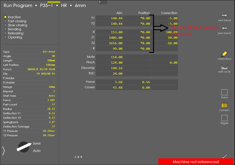
Homing Procedure in RA
Homing can be done in RA software either in JOG screen or RUN screen.
When an axis is not homed the position shown is prefixed with a '*', indicating that position is not correct, and axis needs to be homed.
When user enters RUN screen and axes are not homed, then 'Machine not referenced' message appears in the bottom right of the screen.
-
Make sure the emergency button is released and pump is ON.
-
After reaching the RUN screen 'Machine not referenced' message appears.
Case 1 (RAM position below reference mark):
-
Press the Start button, RAM moves up in search of reference mark and backgauge axis also starts homing in sequence entered in machine parameters (Axis parameters → Homing parameter → Sequence).
-
The '*' prefix disappears for axes position (if homed) in numeric screen.
-
Now if reset (UP pedal) is pressed the backgauge moves to commanded position and program is ready to RUN.
Case 2 (RAM position above reference mark):
-
Press the Start button, RAM moves up in search of reference mark and backgauge also starts to home in sequence entered in machine parameters. As the reference mark is below the RAM, RAM moves up till mechanical upper dead point (beyond this point lag error increases as despite giving command RAM will not be able to move) and stops as no reference pulse is received.
-
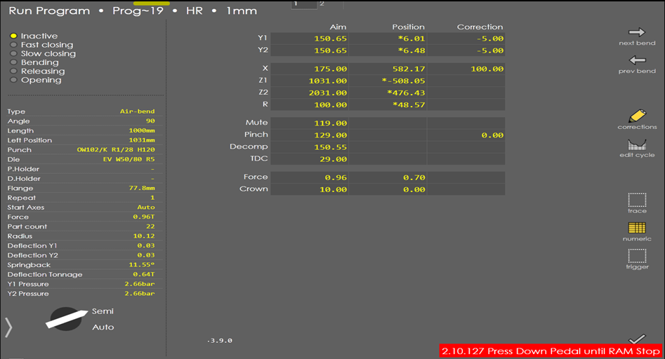
Now message 'Press Down pedal until RAM stops' appears.
-
RAM moves down in search of reference mark as down pedal is pressed.
-
While RAM moves down and the reference mark is found, the homing process of RAM (Y1, Y2) is not completed as it is advised to obtain the reference signal when RAM moves in same direction (UP in this case). Now the controller goes to stop mode and STOP LED (RED LED) glows in the panel.
-
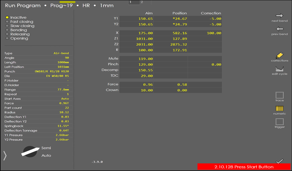
Now message 'Press Start button' appears. When Start button is pressed RAM moves up and completes homing after finding reference mark while moving in UP direction.
-
Now pressing UP pedal (reset) the backgauge moves to the target position and program is ready to RUN.
| Homing can also be done from JOG mode following the same procedure. |
After reaching UDP without finding reference mark, "Press Down Pedal until RAM stops" appears as mentioned below:
When reference mark is found while RAM moves down, "Press Start Button" message appears as mentioned below:
Homing Direction change
In case the operator knows that RAM is above the reference mark and wants to avoid the default upward movement of the RAM then operator can force a change in homing direction by following these steps:
-
Enter RUN or JOG screen, emergency button must be in released state and pump must be ON.
-
Now make sure machine is in stop condition (RED LED must glow in panel), if not in stop condition press the stop button and then press down pedal for 5 seconds.
-
'Homing dir down, release foot pedal' message appears. Release the foot pedal.
-
Now 'Press down pedal until RAM stop' message appears.
-
Press the Start button and then press down pedal.
-
RAM stops after detecting the reference pulse, homing is not yet completed as the reference pulse must always be found when is moving UP.
-
'Press start button' message appears. Now after pressing start button RAM moves UP, finds the reference pulse and homing will complete.
For machine operators
| While homing (when RAM moves down in search for reference pulse) if the footpedal down is not pressed continuously or the RAM movement is unstable there are chances for not detecting the reference pulse in this case RAM keeps moving down and if tools are mounted in the machine it may collide. |
Hence operator must monitor the RAM when moving down and in cases where operator feels the reference pulse has not been detected despite RAM moving down significantly, operator must stop pressing down pedal. Operator must stop pressing Down pedal and press the emergency button, then release the emergency and press reset (Up pedal) to ON the pump, and again press reset (Up pedal). Now on pressing the start button, homing will start with RAM moving up (default homing direction).
RAM synchronization error
In some cases, due to unstable movement the Y1 Y2 difference exceeds the allowed Y1 Y2 difference and RAM Sync error occurs and RAM cannot be moved in RUN or JOG mode. In these cases, it is required to login to machine parameters with service access level and enter diagnostic mode and manually move the RAM, hence operators cannot handle this error on their own. Hence in RA there is a feature provided which forces homing to happen for Y1 Y2 (without restarting the machine), so that operators can handle RAM sync error without resorting to service person.
How to handle RAM Synchronization error
-
Once RAM Sync error occurs, it is not possible to move RAM in run mode.
-
Now operator must press emergency button and press Up pedal for about 5 sec until the Y axis position is prefixed with '*'. This means homing for Y axis will start once again.
-
Now operator can release the emergency, press reset (Up pedal) to ON the pump and press start button to start the normal homing process.
-
Now RAM moves up in search reference mark and normal homing process starts as mentioned above.
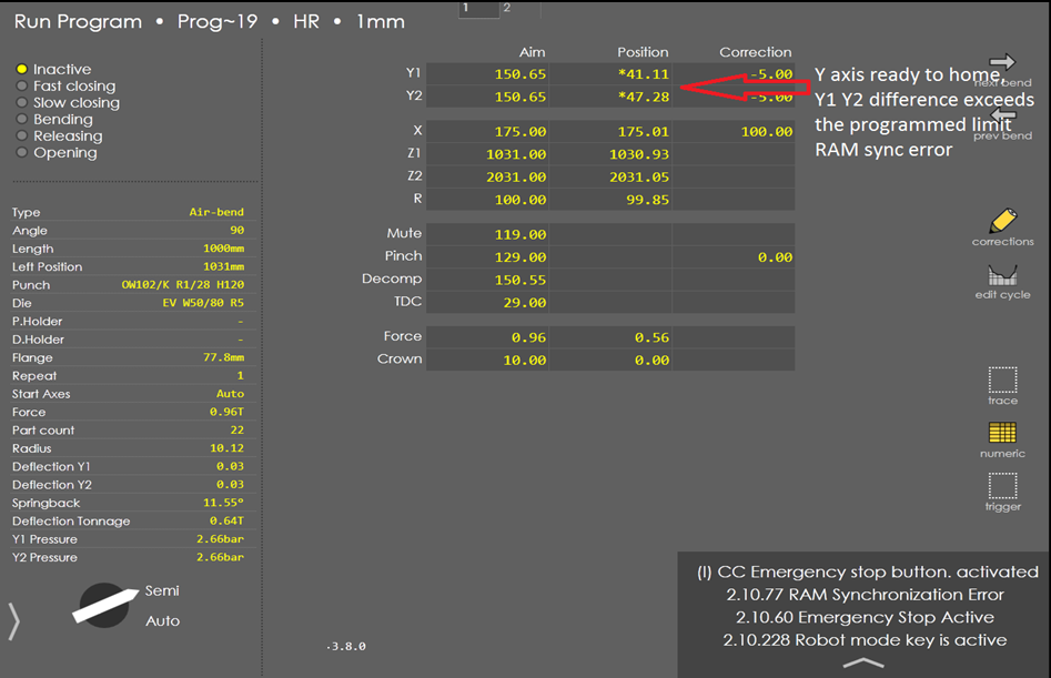
Conclusion
As homing when RAM position is above the reference mark is a two-step process, it is advised to lower the RAM before restarting or powering off the machine in order to complete homing quickly when machine is powered on next time.
Generally, when the homing command is activated, all the backgauge axis will start to move in the homing direction (Safe direction, selected in homing parameter). If the backgauge is near to the tools during homing, then the movement of the R - axis may result in collision with tools. In order to avoid this type of collision the X-axis will be homed first with Sequence number as 1 (default value of parameter) and other R & Z axis will be sequence number 2 (default value of parameter), to follow the homing process.
Home Parameter

Count direction
Range |
Up/Down |
Default |
Up |
Units |
|
Access |
Administrator |
Function
This parameter defines encoder pulse counting direction.
Description
This parameter is used when the encoder pulse counting direction needs to be reversed.