
General
Valve selection

Valve parameter ID
Range |
None / hoerbiger PSL no feedback / hoerbiger PSH no feedback / hoerbiger PIL-NG10\ hoerbiger PIL-NG06 / hoerbiger PIH-NG06 / Rexroth external amplifier 8LPM, Rexroth external amplifier 16LPM, Rexroth external amplifier 32LPM |
Default |
Hoerbiger PSL no feedback |
Access |
Administrator |
Function
This parameter selects the type of valve used in the machine.
Description
Depending on the type of the valve selected in this parameter, corresponding valve parameter table is loaded into the controller.
Valve control amplifier
Range |
VDrive 106 / External |
Default |
VDrive 106 |
Access |
Administrator |
Function
The valve control amplifier controls the hydraulic valve that regulates the flow and pressure of hydraulic fluid to the cylinders that drive the press brake’s ram. The amplifier helps manage the precise movement of the press brake’s ram, which ensures smooth and accurate bending operations.
The Valve control amplifier regulates the ram movement.
Description
It is used to control the ram movement.
External amplifier type
Range |
PVR6 / EV2D / CybVA 6 |
Default |
PVR6 |
Access |
Service |
Precondition
The option to select External amplifier type will only be available when the Valve control amplifier is set to External (Y-Axis Parameters > General > Valve control amplifier).
Function
External amplifier type defines the type of the valve control amplifier.
General
Machine type
Range |
Demo/Hydraulic/Hybrid/Electric |
Default |
Hydraulic |
Units |
|
Access |
Administrator |
Function
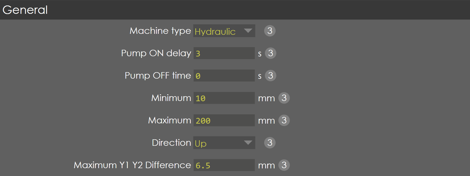
This parameter defines the type of machine in which the controller is deployed.
Description
Depending on the type of the machine, the internal PLC functions are activated automatically. The controller supports the following type of machines:
-
Demo - used for table testing with Y1 & Y2 as normal servo motor axis
-
Hydraulic - used for normal CNC Hydraulic Press Brake machines
-
Hybrid - used for special purpose Hybrid Press Brake machines
-
Electric - used for Electric Press Brake machines
| When machine type is set to Electric, Electric brake parameter is visible in Y-Axis parameter settings page. |
Pump ON delay
Pump OFF time
Range |
0-10000 |
Default |
120 |
Units |
seconds |
Access |
Administrator |
Function
This parameter defines the pump off time during idle running of the induction motor.
Description
If there is no operation is carried out during this specified time, the pump will automatically be turned OFF. If the operator forgets to hit the emergency stop before leaving, this function will be very useful to save the energy.
This function is not implemented in the internal PLC, since the logic of Pump ON & OFF varies depending on OEM’s.
But still this parameter is available in the PLC as 'YParam.General.PumpIdleRunTime' for the OEMs to write their own logic.
Minimum
Range |
0-9999 |
Default |
30 |
Units |
mm |
Access |
Administrator |
Function
This parameter defines the minimum position the RAM can be moved to.
Description
This value is used as a negative software limit. When the start button on the control is pressed the control checks all Y-axis parameters, which are programmed or computed. If a programmed or computed Y-axis value is smaller than Y-min, the value is limited at the Y-min value and an error message appears on the screen.
'Y-Axis - Target < Negative software Limit'
| This programmed minimum position should be below the mechanical top dead centre, to make sure this position can always be reached. |
Maximum
Range |
0-9999 |
Default |
200 |
Units |
mm |
Access |
Administrator |
Function
This parameter defines the maximum position the RAM can be moved to.
Description
This value is used as a positive software limit. When the start button on the control is pressed the control checks all Y-axis parameters, which are programmed or computed. If a programmed or computed Y-axis value is greater than Y-max, the value is limited at the Y-max value and an error message appears on the screen.
'Y-Axis - Target > Positive software Limit'
Direction
Range |
UP/DOWN |
Default |
UP |
Units |
|
Access |
Administrator |
Function
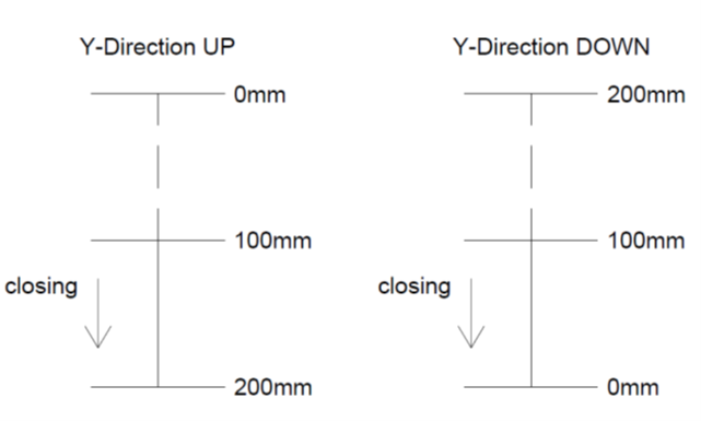
This parameter defines the count direction of Y-axis linear scales with respect to the bottom of the table.
Description
If this parameter is configured as 'UP', then the Y-axis position value is increased when the beam approaches the bottom of the table (i.e.,) closing. If programmed 'down', then the Y-axis position value is decreased when the beam closes.
Maximum Y1 Y2 difference
Range |
0-50 |
Default |
6 |
Units |
mm |
Access |
Administrator |
Function
This parameter defines the maximum allowed difference between the left beam position (Y1) and the right beam position (Y2).
Description
This value is the maximum position difference allowed between Y1 and Y2 axis and if the difference exceeds beyond this value the controller will stop and an error message appears on the screen.
'RAM Synchronization error'
Advanced
Tandem
Range |
ON/OFF/ROBOT |
Default |
OFF |
Units |
NA |
Access |
Administrator |
Function
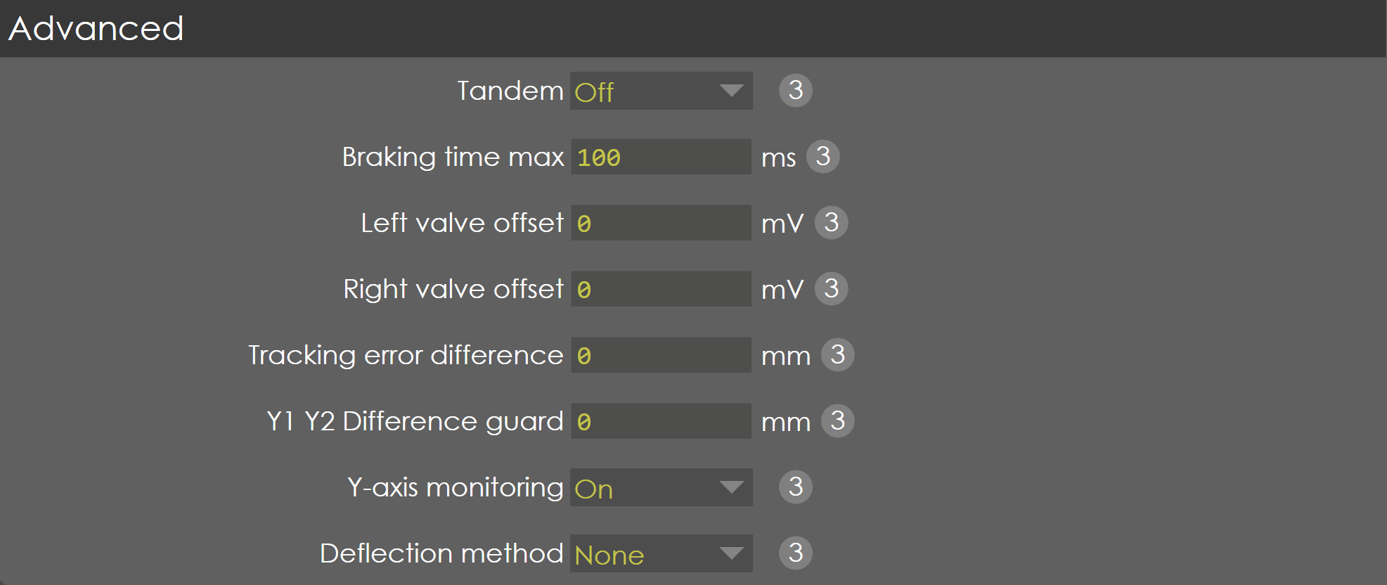
This parameter is not validated.
Description
NA
Braking time max
Range |
0 - 1000 |
Default |
0 |
Units |
ms |
Access |
Administrator |
Function
This parameter defines the maximum allowed braking time of the ram.
Description
The stopping of RAM during emergency condition or foot pedal released etc., can be programmed using this parameter.
Left valve offset
Range |
-500 to 500 |
Default |
0 |
Units |
mV |
Access |
Administrator |
Function
This parameter is used to change the valve offset for Y1 axis.
Description
NA
Right valve offset
Range |
-500 to 500 |
Default |
0 |
Units |
mV |
Access |
Administrator |
Function
This parameter is used to change the valve offset for Y2 axis.
Description
Tracking error difference
Range |
1-100 |
Default |
0 |
Units |
mm |
Access |
Administrator |
Function
This parameter defines the maximum allowed difference between the tracking error of Y1 and Y2.
Description
Tracking error is the difference between the computed cycle and the measured cycle. This parameter serves to set the maximum allowed difference between the tracking errors of Y1 and Y2. If this difference is exceeded, a warning is issued on the screen and the PLC flag 'YParam.LagError_Op' is set. This PLC flag can be used in the PLC program, for instance to stop the machine.
If this parameter is programmed to zero, this mechanism is not used.
Y1 Y2 difference guard
Range |
0-999 |
Default |
0 |
Units |
mm |
Access |
Administrator |
Function
This parameter defines the guard, the maximum difference between Y1 and Y2.
Description
The difference between the linear scale of Y1 & Y2 readings are monitored, if the difference becomes larger than the programmed value the corresponding PLC 'flag YParam.Y1Y2Diff_Op' is set. This flag can be used in the PLC program, for instance to stop the machine.
If this parameter is programmed to zero, this monitoring is not done.
Y axis monitoring
Range |
ON/OFF |
Default |
ON |
Units |
NA |
Access |
Administrator |
Function
This parameter is not validated.
Description
NA
Defelction method
Range |
None / Pressure sensor |
Default |
None |
Units |
NA |
Access |
Administrator |