
Feedback
Linear scale
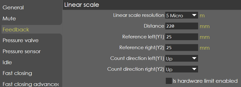
Linear scale resolution
Range |
1 Micron / 5 Micron |
Default |
5 Micron |
Units |
Microns |
Access |
Administrator |
Function
This parameter defines the resolution of linear scales.
Description
The resolution of linear scales used in Left (Y1) and Right (Y2) side of RAM is defined here and it supports 1 micron or 5 microns resolution. Please make sure that both the sides use the same resolution of linear scale.
Distance
Range |
0.001-10000 |
Default |
220 |
Units |
mm |
Access |
Administrator |
Function
This parameter defines the length of the linear scale.
Description
This parameter will make sure the controller is able to read the counts for the entire length of the scale.
Reference left (Y1)
Range |
0-9999.99 |
Default |
25 |
Units |
mm |
Access |
Administrator |
Function
This parameter defines the reference offset position of Y1-axis left side linear scale and parallelism adjustment.
Description
With respect to this value, the Y1-axis position is displayed on the screen after passing the reference mark.
| This value must be greater than the mechanical travel distance on the scale from reference mark position to the scale end. This travel distance must also be greater than the mechanical travel of the cylinder from reference point position to the upper dead point mechanical in the cylinder. Make sure that when the cylinder is on the mechanical upper dead stop the Y-axis value readout is between 5 and 10 mm. |
Reference left (Y2)
Range |
0-9999.99 |
Default |
25 |
Units |
mm |
Access |
Administrator |
Function
This parameter defines the reference offset position of Y2-axis left side linear scale and parallelism adjustment.
Description
With respect to this value, the Y2-axis position is displayed on the screen after passing the reference mark.
Count direction left (Y1)
Range |
Up / Down |
Default |
Up |
Units |
NA |
Access |
Standard |
Function
This parameter defines encoder pulse counting direction of Y1 linear scale.
Description
Generally, the position counting of Y1 should be up-counting when the beam is moving down. This parameter is used when the encoder pulse counting direction needs to be reversed.
Count direction left (Y2)
Range |
Up / Down |
Default |
Up |
Units |
NA |
Access |
Standard |
Function
This parameter defines encoder pulse counting direction of Y2 linear scale.
Description
This parameter is used when the encoder pulse counting direction needs to be reversed.
Is Hardware Limit enabled
Range |
Checked / Unchecked |
Default |
Unchecked |
Units |
NA |
Access |
Administrator |
Function
This parameter enables/disables the hardware limit switch of Y-axis.
Description
The controller is equipped with both Negative and Positive hardware limit switch input individually for Y1 and Y2 axis. If the hardware limit is active, the controller expects both the positive & negative inputs, else the error message appears on the screen:
-
If positive switch is absent - 'Y Axis - Positive hardware limit switch active'
-
If negative switch is absent -' Y Axis - Negative hardware limit switch active'
| For detailed description of hardware switches refer RA SmartCore 800 manual. |
General
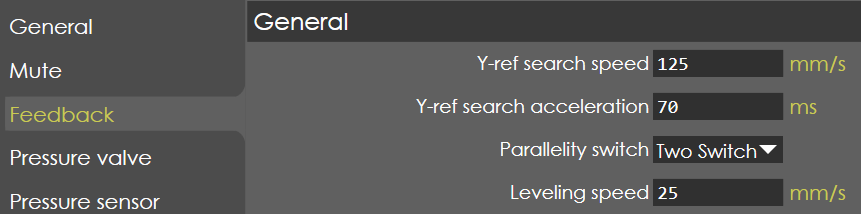
Y-ref search speed
Range |
10-250 |
Default |
125 |
Units |
mm/s |
Access |
Administrator |
Function
This parameter defines the speed with which the beam moves in upward direction during reference search cycle.
Description
When the reference search cycle of the Y-axis is started, the beam is moved in the upward direction with the speed programmed here. The sequence of the complete reference cycle depends on the position of the beam:
-
If the beam was positioned below the reference point, the Y-axis will reach the reference point and set the position.
-
If the beam was positioned above the reference point, the beam will also move upwards with the programmed speed. When the beam reaches the mechanical upper dead point, the control will detect after a short period that there is no movement and will stop the reference command. Now, when the foot pedal close is pressed, the beam start move downwards with closing speed (specified in pressing parameter).
-
During downward movement, when the beam crosses the reference mark, a stop command is issued, and the controller goes to stop mode. At this position, it is made sure that the beam is below the reference point. Now, when a start command is given the beam moves in the upward direction, crosses the reference mark and set the position of Y-axis to complete the reference cycle.
| This method of reference cycle make sure that the Y-axis position is always set during the upward movement(while referencing) of the beam. |
Y-ref search acceleration
Range |
NA |
Default |
70 |
Units |
ms |
Access |
Administrator |
Function
This parameter defines the time in which the beam reaches max speed from zero speed during reference search cycle.
Description
NA
Parallelity switch
Range |
No Switch / Two Switch |
Default |
No Switch |
Units |
NA |
Access |
Administrator |
Function
Two switches mounted across Y1 & Y2 is used for Parallelism indication of the RAM used before Y-axis references are passed.
Description
If the parameter is selected as 'Two Switch', then the switch inputs are connected to digital inputs of SmartCore. With this inputs the control has an indication of the parallelism of the RAM. When this inputs are active (switch closed) the RAM parallelism is OK.
If left side switch is open, then the RAM is down in left side and up in right side or vice versa. Depends on the switch status, the RAM is moved in one side to make it parallel at lower speed and then pass the reference.
When the parallel switch is not mounted (No switch selected) the control will not use this input before the references are passed.
Levelling Speed
Range |
10 to 250 |
Default |
25 |
Units |
mm/s |
Access |
Administrator |
Function
This parameter is not yet validated.
| This parameter appears only if two switch is selected in parallelity switch parameter. It is speed at which RAM moves if Y1 and Y2 are not parallel before referencing(homing). |
Description
For example, if left side parallelity switch is open, then the RAM is down in left side and up in right side or vice versa. Depending on the switch status, the RAM is moved in one side to make it parallel at this entered speed and only then homing starts.